


Jocelyn
06-01-2023
Quick Optimal Start: How to Minimize Wireless Dropouts
Are you still curious about how to deal with wireless dropouts? Now you do not need to worry anymore because this blog will dive into the selection of suitable gear and a brief guide for setup, which is helpful to minimize wireless dropouts and optimize your rack workflow at the very start.

In the last blog, Demystify Wireless System Signal Dropouts, we talked about why wireless dropouts occur and what elements should be considered when troubleshooting. Today, this blog will focus on how to minimize wireless dropouts with quick optimal hookups. Here at Phenyx Pro, we strive to engineer gear with rock-firm wireless coverage. To maximize wireless excellence, you are suggested to follow the guideline below for proper system hookup and logical sound check.
Choose The Right Gear
From the last blog, we learned that antenna placement and signal strength should be taken into account to achieve minimal wireless dropouts. In fact, people can take advantage of professional equipment like an antenna distribution system or antenna combiner to accomplish this. However, some less advanced wireless systems are naturally more difficult to resist interference and easier to introduce intermodulation distortion during the multiset operation. Therefore, it is essential to choose the right gear based on your applications. If you are going to establish a setup in a complicated wireless environment or medium-to-large scale events, you should focus your search on systems with the auto scan function and true-diversity circuitry.
We have also developed advanced wireless microphone systems and optimal antenna solutions to upgrade your rack workflow. So let’s see how those gears can handle your wireless problems.
Gear for Setup: True Diversity
True diversity is a more effective way to receive clean wireless signals. The true diversity circuit uses two antennas to jointly receive the signal from a single transmitter. Then, these two antennas will automatically detect and switch to the stronger signal according to the local RF environment. Hence, not only can radio waves propagate more stably, but the signal-to-noise ratio (SNR) is higher than normal non-diversity ones.
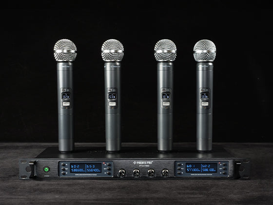
True diversity systems are one of the best options for demanding wireless performance to ensure satisfaction. At Phenyx Pro, we have also launched our true diversity series, the PTU-1U and PTU-2U wireless microphone systems. Additionally, the PTU-1U/2U handheld microphone features an RF power switch which enables the mic to emit 1mW in the LO mode or 10mW in the HI mode. This adjustment gives you more chances to choose a favorable Tx power according to different circumstances. For instance, you can turn on the LO mode after pairing up the mic with its receiver, and no worry would bother you whether the preset channels would be grabbed and occupied when turning off the stand-by microphones.
Please read these previous blog posts for more details.

Gear for Setup: Antenna Distribution
When you need to use multiple wireless microphone systems simultaneously, the antenna distribution system plays an important role in navigating a congested RF environment as it can fend against intermodulation to some extent in multiset operation and boost the signal gain to stretch operation range. In the case of wireless in-ear monitor systems, you will need an antenna combiner system instead.
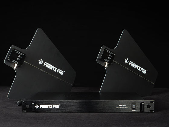
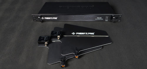
We also offer such a solution to our users, the PAS-225X antenna distribution system. It is a 4-way active antenna distribution system operating in 400 — 950MHz UHF band, which is compatible with all UHF wireless microphone systems within this frequency range and connects up to 8 receiver antennas together. It splits wireless receiving antennas and unifies signal reception by the pair of directional antenna paddles, which can avoid mutual interference of adjacent antennas in multiset operation and minimize noise pickup because of off-axis reject. Then, the splitter/distributor allocates received signals after amplifying their gain and feeds them respectively to each receiver.
Additionally, each directional antenna paddle with log-periodic dipole array (LPDA) boasts up to 8dBi forward amplified gain, which is useful to amplify the signal to compensate for the loss and customize receiving range. But again, remember to set an appropriate amount of gain (suggest more than 3dB) to generate clearer signals because you need to take into account that more range is susceptible to more noises.
To be honest, the PAS-225X is not always almighty, but the proper operation can maximize its effect. Please read the following blogs if you would like to learn more about it.
Besides, the digital wireless microphone system can solve the limitations of the linear signal by encrypting audio signals to digital ones. Phenyx Pro is expected to launch such premium gear in the near future - so stay tuned!
A Brief Setup Guidance
Admittedly, a high-end setup can certainly ensure signal purity and signal gain, but it is not always infallible to fend against tricky dropouts. Some defects can still be remedied by studio post-adjustment, but it is hard to have one more chance in whatever a live performance, sermon, speech, etc. Hence, pre-tuning by backstage engineers is important to a flawless live show. Below is a brief guide that will help you hassle-freely set up your rack and do a logical sound check for troubleshooting.
Antenna Placement
After choosing the above formidable gear to avoid dropouts, proper antenna placement can alleviate possible wireless troubles during sound check. So please follow these useful tips below to set your antennas properly.
- Select the site away from the signal-crowded region and base stations.
- Use unidirectional antennas as much as possible and connect each one in specified frequency bandwidth with your compatible systems.
- Place receiver directional antennas as close as possible to transmitters, but the distance is suggested to be more than 10ft/3m to avoid intermodulation as much as possible due to overloaded RF power occurring to the receiver.
- Place receiver antennas parallel to transmitters.
- Place directional antennas oriented to transmitters.
- Remove metal objects and other barriers in the line of sight.
- Place antennas in a higher place to make sure no or fewer people are in the line of sight to block the signal.
- Keep the rack away from unnecessary electronics at least 60cm/3ft to avoid interference.
- Use proper low-loss BNC antenna cable to remotely mount receiver antennas.
Effective Steps for Sound Test
After proper antenna placement with the optimal line of sight, we can mitigate external factors invoking RF problems. In this way, you can do an effective sound test to find if a defective component is present in your rack workflow. Here are logical tips you can follow to locate the cause.
- Power on your system and initiate the auto scan function of a receiver to locate a clean frequency. In manual setup, check out major users of local radio frequencies to avoid the crowd and find a locally-vacant frequency to operate.
- After pairing up receivers and transmitters, test each problem separately one by one to see and check if all indicators of receivers and transmitters display normally.
- For a problematic mic, try other frequency channels and pair it up again to decide whether it is a frequency problem or not.
- If you get several test failures, check if the power supply voltage is stable, restart the wireless receiver and repeat the above setup to see whether it is feasible.
- If the above steps are inoperative, move the problematic wireless microphone system to a different place, restart the system, and sync several times again. If everything goes on normally, the cause might be outside interference in the original location. But if wireless dropouts still occur frequently, please contact the service center to troubleshoot or replace the defective components.
*Note: Electromagnetic interference arising from too low or unstable voltage can lead to excessive static noise. Reducing the plug load will also enable stable and sufficient power to the system while possibly reducing static noise.
*Note: For multiset operation, please check if the whole system is working normally before you add other wireless systems, antenna distribution and other devices one by one until a complete rack workflow is set up.
Case Study
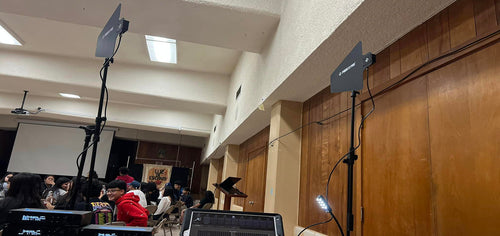
When you get here, you must have a clearer mind to deal with a dropout. Let’s take the below case to make a simple judgment. Please comment on how great is the rackmount workflow and what improvements can be made.
Advantages
The engineer wisely uses our cutting-edge products, PTU-1U true diversity system and PAS-225X antenna distribution system, to alleviate most RF problems. In addition, he set two antennas about 2m/6.5ft away from each other, which is appropriate.
Recommendations
- To mitigate cross-polarization fade, antenna paddles should be lowered to where parallel to microphone transmitters but high enough to avoid the crowd.
- Since an unobstructed space of 60cm/3ft around each antenna paddle is desirable, it is recommended to move the control desk a little behind the rack.
Above all, we provide you with effective gear and a brief guide to mitigate possible RF problems. If you have any questions, you are welcome to our service center. Phenyx Pro also looks forward to your experience and story about wireless systems shared with us via email, Instagram and Facebook.
Author

Jocelyn