


Jocelyn
23-12-2022
Demystify Wireless System Signal Dropouts
It’s many people's worst nightmare to have a wireless system cut out in a show or on stage. Today we will systematically walk through the possible causes for wireless signal dropouts and essential factors to consider when troubleshooting.

A wireless dropout annoys live audio performers most from time to time. And sometimes, even an engineer can’t tell what causes a wireless nightmare straightforwardly and how to prevent it.
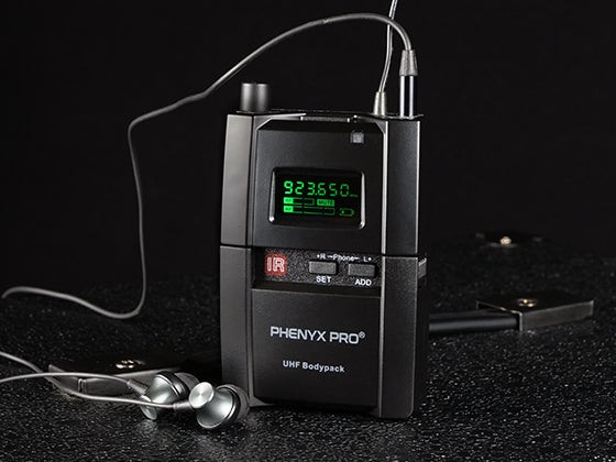
Admittedly, a less advanced wireless microphone system is more susceptible to wireless dropouts. For example, our hands are tied when other interference sources occupy the preset channels on the fixed frequency PTU-5000 system. Moreover, wireless systems exhibit various anti-interference abilities due to different circuitry designs (true diversity vs. non-diversity). Nonetheless, we found most signal dropouts can be resolved by proper operation, appropriate antenna placement, and logical sound check in advance. Thus, it is a pity to rush to the conclusion that you have received a defective product when you encounter signal interference.
In this blog, we will learn why a wireless dropout occurs and what factors we should consider when troubleshooting.
Why Wireless Dropouts Occur
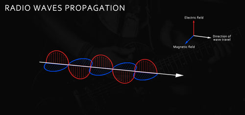
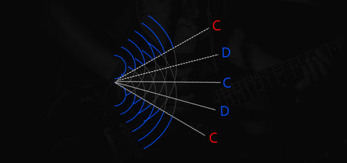
The microphone is a transducer that converts sound waves into electrical impulses and enhances the electrical signals to accomplish sound transmission. Such electrical currents become electromagnetic waves with electric and magnetic components oscillating and traveling in their respective fields, as shown in the diagram below. This is how radio signal is transmitted and received in the wireless microphone system. And radio waves are susceptible to external interference sources, so they may be reflected or absorbed in their sinusoidal motion. Having learned about the wireless signal, we can now further understand how a wireless dropout occurs.
Multipath cancellations. Since radio waves may be reflected, if they encounter too many barriers when traveling, especially metal objects, multipath cancellations will be generated. To be specific, two or more sound waves work against each other as the sum of their relative amplitude and phrase approaches or reaches zero after multiple reflections. In environmental propagation, the points of cancellation are called dead spots. Thus, this type of ineffective transmission is desperation beyond all question.
Signal absorption. Radio waves can be absorbed, especially by any particle that can carry electric charges, for instance, water. Therefore, the transmission of radio signals might be severely affected by moist environments, wet weather, and even human bodies that are primarily composed of water. A great example would be when users cover the antenna or the bottom of a transmitter with their hands. The statistic shows that the effective transmission would reduce by more than 50% and may cause a dropout.
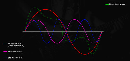
Electromagnetic interference. According to the diagram below, the RF signal keeps oscillating in different amplitudes, and the nonlinear circuits generate harmonics that are multiples of fundamental. When the bandwidth is inadequate, other adjacent frequencies may bring nonlinear elements and/or leaked signals and even splatted energy to your signals. In this condition, different harmonics interact and affect each other to produce unwanted frequencies that lead to signal distortion and interference. We call this frequency regrowth phenomenon intermod (IMD). Intermodulation distortion (IMD) is a common cause of wireless interference.
As the radio wave keeps changing its vibration, the spectrum changes correspondingly. The overstepping vibration mentioned above brings electromagnetic interference (EMI). Typically, there are various outside interference sources to deteriorate the situation, such as broadcast stations, other wireless audio equipment (in-ear monitors and intercom systems), and electronics like TVs, cell phones, LED lights, etc.
Some customers have questioned why 600MHz-band devices can interfere with a 500MHz-band system. Now you may have the answer — spectral regrowth leads to splatter noise and power. Also, there are some doubts about why we can not simultaneously link up wireless systems as many as we advocate. That is because the IMD limits our setup with inadequate bandwidth in the spectrum, which is relevant to wavelength and power. By the way, if digital devices (CD players, computers, digital audio processors, etc.) are installed very close to a wireless mic receiver, strong RF signals they emit (theoretically, IMD) tend to interfere with the receiver. For transmitters, GSM cellphones and the PDA worn by presenters are common threats that should be avoided. In a band in which vocal, guitar, drum and other sound mix together, a designated signal could be unpurified with possible IMD hazard. This is because when microphones get too close, power generates and increases useless sideband signals, which causes unwanted noises during sound pickup.
In short, electromagnetic interference brings intermodulation distortion to garble signal reception, and the root is that the analog circuitry relies on linear signals. Thus, such deficiencies could not be avoided. You can use a spectrum analyzer to help find a clean frequency to operate. Otherwise, a digital wireless system might be able to do a better job, for it cipher and decipher digital signals during transmission and reception, which is a different way from the analog one.
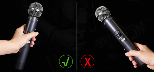
Antenna issue. First of all, antennas are divided into the omnidirectional antenna and directional antenna according to the signal pickup range. And the widely-preferred latter one features extraordinary off-axis rejection. Moreover, the antenna, especially the directional type, has to be oriented properly to wireless transmitters to make effective signal reception within the direct line of sight and operating range. Last but not least, microphone angles may create a cross-polarization fade. This means that different microphone angles might cause some drop in RF input power for receiving antennas. Then, a cross-polarization dropout occurs. In other words, if the transmitting part and its receiving antenna are aligned with each other, the transmission is maximized.

Besides, signal loss and insufficient signal strength are not the keys to producing dropouts but still influence signal transmission and reception. When the distance between the transmitter and receiver is too far, the signal would not be strong enough and have much signal loss to transmit complete content.
Troubleshooting Elements to Consider
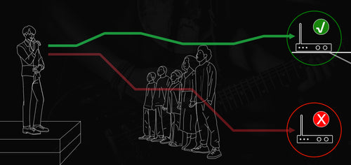
Line of sight. The microphone should be as close as possible to the receiver to ensure great signal strength and raise the signal-to-noise ratio (SNR). Meanwhile, clean up any barriers in their direct route to each other, which may cause possible signal reflection or absorption, especially metal material.
Proper Operation. Since human bodies may absorb the signal, please avoid covering the bottom of a transmitter with your hands.
Frequency. Primarily, avoid a crowded spectrum and select the locally-vacant and distant frequency for using a microphone. As for the site selection, choose to stay away from various base stations and crowded towns. Stay away from cellphones, computers, televisions and other electronics as far as possible that may generate electromagnetic interference. As for the wireless microphone system, initiate its auto-scan function to assist you in finding a clean desired frequency to operate hassle-freely, while for manual setup, using a spectrum analyzer can help you. In brief, please ensure each microphone channel has sufficient bandwidth. If you have a slack budget, the band-pass filter can be a great buy to filter out-of-band signals, which means the desired signal could be purified by receiving fewer additional signals.
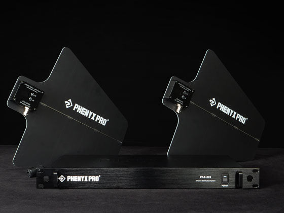
Antenna placement. Orientation, height and space should be taken into account. As for orientation, use the directional antenna with extraordinary off-axis rejection whenever possible to reject unnecessary signal reception. And remember to orient the front end of the antenna to the microphone transmitters directly. As for height, antennas should be mounted at a similar height with microphones for better reception. For the sake of reducing cross-polarization fade, adjust the antenna angle and keep antennas parallel to microphones. It might be a nightmare if the antenna is vertical to them. When cross-polarization dropout occurs frequently, you can even use circularly polarized helical antennas to deal with it.
As for space, antennas should be separated from each other by a minimum of one-quarter wavelength — about 16 inches (40cm) for VHF units and about 4 inches (10cm) for UHF units. Stretching the space can sometimes promote signal reception. If multiple gears need to be linked up simultaneously, it is wise to front mount or remotely mount receiver antennas. By the way, antenna distribution merges multiple receiving antennas into its directional antenna paddles, which can avoid interlaced antennas on the rack to optimize wireless reception.
Signal strength. Proper distance between transmitters and the receiver is preferred to guarantee a strong, pure signal as much as possible. Otherwise, when microphones are too far away from their receivers or coaxial cables are needed, you'd better use low-loss cables to compensate for signal loss. Meanwhile, you can also amplify the signal in a proper amount after calculation. In addition, proper transmitting power (Tx power) can prevent IMD aggravation to ensure signal purity.
Conclusion
Today, we have learned about reasons why wireless dropouts occur and elements to consider for troubleshooting. In the next blog, we will provide you with brief optimal setup guidance and useful tips so that you can quickly browse through to set up your rack and do a logical sound check in actual practice. If you want to acquire more information, please leave a comment below to let us know what you want to know.
Author

Jocelyn